
Introduction
In this Project, we are going to make a Traffic light with an LCD display controlled by Arduino, The traffic light is a crucial component of modern transportation systems, providing safety and order to vehicles and pedestrians. In this project, we will create a traffic light using an Arduino UNO microcontroller and three LEDs (red, yellow, and green). Additionally, an LCD I2C 160A display will be incorporated to display relevant information during the process.
Hardware Required
| Components | # | Buy Links |
|---|---|---|
| Arduino UNO | 1 | Buy Now |
| LCD I2C 160A display | 1 | Buy Now |
| LED Red, Green, and Yellow | 1,1,1 | Buy Now |
| Resistors 220Ω | 3 | Buy Now |
| Jumper Wires | Few | Buy Now |
| Breadboard | 1 | Buy Now |
What is I2C Module?
The I2C Serial Interface Adapter Module is designed to convert serial signals into I2C signals, allowing the microcontroller to interface with I2C-based sensors and devices. It supports communication rates up to 400kHz and can be used with a variety of microcontrollers.
Specifications:
- Input voltage: 5V
- Maximum baud rate: 115200bps
- I2C bus frequency: up to 400kHz
- Supports 7-bit and 10-bit addressing modes
- Small form factor: 25mm x 12mm
Features:
- Converts serial signals to I2C signals
- Easy to use and integrate with microcontrollers
- Supports both 7-bit and 10-bit addressing modes
- Can communicate at high speeds up to 400kHz
- Its small size makes it suitable for use in compact designs
- Can be used with a wide range of microcontrollers
Pinout

Pin Configuration of I2C
| Pin Name | Pin Type | Pin Description |
| GND | Power | Ground |
| VCC | Power | Voltage Input |
| SDA | I2C Data | Serial Data |
| SCL | I2C Clock | Serial Clock |
Circuit Diagram
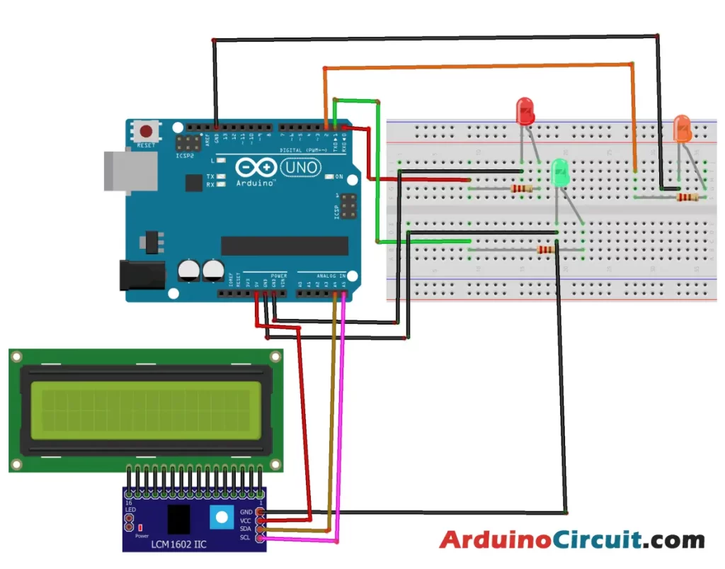
Circuit Connections
| Arduino | LCD display | LEDs |
|---|---|---|
| VCC | VCC | |
| GND | GND | -Ve of all Leds |
| A4 | SDA | |
| A5 | SCL | |
| D1 | Red through R1 | |
| D2 | Green through R2 | |
| D3 | Yellow through R3 |
Working Explanations
The Arduino UNO will control the LED sequence, and timing and display the relevant messages on the LCD display. The red LED will first light for 3 seconds with the message “Stop” displayed on the LCD screen. After this period, the red LED will go out, and the green LED will light up for 3 seconds with the message “Cross” displayed on the LCD screen. Once the green LED goes out, the orange LED will light up for 2 seconds with the message “Cross fast” displayed on the LCD screen.
Installing Arduino IDE Software
First, you will require to Download the updated version of Arduino IDE Software and Install it on your PC or laptop. if you Learn How to install the Arduino step-by-step guide then click on how to install Arduino Button given Blow
Installing Libraries
Now when you are Ready to upload the code, to the Arduino Board you will need first to add the Following Libraries in Arduino, If you Learn How to add the library in the Arduino step-by-step guide click on how to install the library Button given Blow
Code
//For more Projects: www.arduinocircuit.com

#include <LiquidCrystal_I2C.h>

LiquidCrystal_I2C lcd(0x27, 20, 4);

void setup(){
lcd.init();
pinMode(0,OUTPUT); //sets the number 0 digital pin of the Arduino in output mode
pinMode(1,OUTPUT); //sets the number 1 digital pin of the Arduino in output mode
pinMode(2,OUTPUT); //sets the number 2 digital pin of the Arduino in output mode

}

void loop(){
lcd.backlight();
lcd.clear();

digitalWrite(0,HIGH); //red LED lights up
digitalWrite(1,LOW); // green LED goes out
digitalWrite(2,LOW); //orange LED goes out

lcd.setCursor(0, 0);
lcd.print("STOP");
delay(3000);

lcd.clear();

digitalWrite(0,LOW); //red LED goes out
digitalWrite(1,HIGH); //green LED lights up
digitalWrite(2,LOW); // orange LED goes out
lcd.print("Cross");
delay(3000);

lcd.clear();

digitalWrite(0,LOW); //red LED goes out
digitalWrite(1,LOW); // green LED goes out
digitalWrite(2,HIGH); //orange LED lights up
lcd.print("Cross fast");
delay(1000);
}
Applications
- Traffic light systems for small-scale transportation systems such as car parks, private driveways, and private roads.
- Educational purposes for teaching traffic systems and Arduino programming.
Conclusion
In conclusion, the Traffic light with LCD display controlled by Arduino is a simple yet effective project that demonstrates the functionality of a traffic light system in a controlled environment. This project is an excellent educational tool for teaching the basics of Arduino programming and traffic systems. It can also be used for small-scale transportation systems, providing a safe and orderly traffic light sequence.
See Also


