Introduction
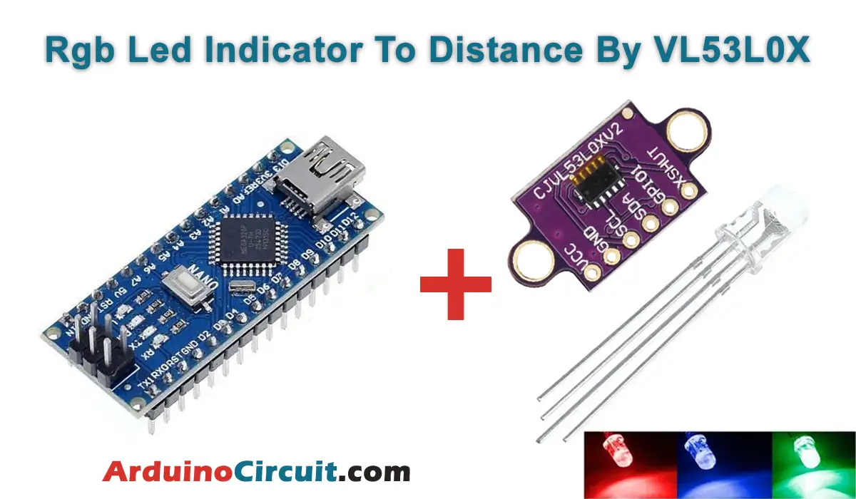
In this project, we will Learn How to make Rgb Led Indicator To Distance By VL53L0X, so basically the RGB LED to indicate the distance measured by VL53L0X time-of-flight sensor. The RGB LED will change its color according to the distance measured by the sensor. The closer the obstacle, the more intense the color will be.
Hardware Required
You will require the following Hardware Components for making Rgb Led Indicator To Distance By VL53L0X.
| Components | # | Buy From Amazon |
|---|---|---|
| Arduino Nano | 1 | Buy Now |
| VL53L0X Distance Sensor | 1 | Buy Now |
| RGB LED (cathode) | 1 | Buy Now |
| Resistor 1K | 3 | Buy Now |
| Jumper Wires | Few | Buy Now |
| Breadboard | 1 | Buy Now |
What is VL53L0X Distance Sensor?
The VL53L0X Distance Sensor is a module that integrates the VL53L0X ToF sensor with a microcontroller, power management unit, and communication interface. The module provides accurate distance measurements, ambient light sensing, and programmable interrupt output.
Pinout

Pin Configuration
| Pin Name | Pin Type |
|---|---|
| VCC | It is the voltage supply pin. |
| GND | It is Ground Pin |
| SCL | It is the digital serial clock input pin. |
| SDA | It is a serial data digital input/output pin for communication. |
| GPIO1 | It is the programmable interrupt output pin. |
| XSHUT | It is an active-low shutdown input pin. |
Specifications
- Operating voltage: 2.8V to 5V
- Range: up to 2 meters
- Accuracy: ±3%
- Measurement rate: up to 60Hz
- Ambient light sensing range: 0.1 to 100,000 lux
- Communication interface: I2C
Features
- Integrated laser emitter and detector
- Low power consumption
- Small form factor
- Interrupt output for range detection and ambient light sensing
- Programmable I2C address
Circuit Connections
The circuit connections for this project are straightforward. Connect the SDA and SCL pins of the VL53L0X sensor to A4 and A5 pins of the Arduino Nano respectively. and connect the vcc and Gnd to 5v and Gnd of Arduino Nano, and Connect the RGB LED’s common cathode pin to the GND pin of the Arduino Nano. Connect the red, green and blue pins of the RGB LED to digital pins 3, 5 and 6 of the Arduino Nano respectively. Use a 1K resistor in series with each of the red, green and blue pins of the RGB LED.
Circuit Diagram
The following circuit shows you the connection of the VL53L0X Multi Sensor with Arduino Please make the connection carefully

Working Explanation
The VL53L0X sensor sends a laser beam to the target object and measures the time taken for the laser to bounce back to the sensor. This time is used to calculate the distance of the object from the sensor. The Arduino Nano receives this distance data from the sensor and based on this data, it controls the RGB LED to change its color accordingly.
If the distance is less than a certain threshold, the LED will change to red indicating the obstacle is too close. and If the distance is between a certain range, the LED will change to yellow indicating the obstacle is closer. If the distance is greater than a certain range, the LED will change to green indicating the obstacle is far.
Installing Arduino IDE Software
First, you will require to Download the updated version of Arduino IDE Software and Install it on your PC or laptop. if you Learn How to install the Arduino step-by-step guide then click on how to install Arduino Button given Blow
Installing Libraries
Now when you are Ready to upload the code, to the Arduino Board you will need first to add the Following Libraries in Arduino, If you Learn How to add the library in the Arduino step-by-step guide click on how to install the library Button given Blow
Code
//For more Projects: www.arduinocircuit.com

const int ledPinRed = 3; // Red LED connected to analogue out pin
const int ledPinGrn = 5; // Green LED connected to analogue out pin
const int ledPinBlu = 6; // Blue LED connected to analogue out pin
// Constants to define the ranges.

const int hueRedLow = 0;
const int hueRedHigh = 255;
const int hueBlue = 170;
const int angleMin = 0;
const int angleSector = 1;
const int angleMax = 360;

const int brightMin = 0;
const int brightMax = 255;

int potValueHue;

int hue, brightness;

const int saturation = 255;
unsigned int r, g, b;
#include <Wire.h>
#include <VL53L0X.h>

VL53L0X sensor;
void setup() {
// Still need to set a baud rate, even for USB.
Serial.begin(9600);
Wire.begin();

sensor.init();
sensor.setTimeout(100);

// Set LED pins to output.
pinMode(ledPinRed, OUTPUT);
pinMode(ledPinGrn, OUTPUT);
pinMode(ledPinBlu, OUTPUT);

sensor.startContinuous();
}

void loop() {
potValueHue = map(sensor.readRangeContinuousMillimeters(), 1000, 0, 0, 360);

hue = constrain(map(potValueHue, angleSector, angleMax – angleSector, hueRedLow, hueBlue), hueRedLow, hueBlue);
brightness = constrain(map(potValueHue, angleMin, angleSector, brightMin, brightMax), brightMin, brightMax);

brightness = brightness – constrain(map(potValueHue, angleMax – angleSector, angleMax, brightMin, brightMax), brightMin, brightMax);

// Do the conversion.
HSBToRGB(hue, saturation, brightness, &r, &g, &b);

analogWrite(ledPinRed, r);
analogWrite(ledPinGrn, g);
analogWrite(ledPinBlu, b);

Serial.print(” bright=”);
Serial.print(brightness);
Serial.print(” hue=”);
Serial.print(hue);
Serial.print(” red=”);
Serial.print(r);
Serial.print(” green=”);
Serial.print(g);
Serial.print(” blue=”);
Serial.print(b);
Serial.println(“”);
delay(50);
}

void HSBToRGB(
unsigned int inHue, unsigned int inSaturation, unsigned int inBrightness,
unsigned int *oR, unsigned int *oG, unsigned int *oB )
{
if (inSaturation == 0)
{
// achromatic (grey)
*oR = *oG = *oB = inBrightness;
}
else
{
unsigned int scaledHue = (inHue * 6);
unsigned int sector = scaledHue >> 8; // sector 0 to 5 around the color wheel
unsigned int offsetInSector = scaledHue – (sector << 8); // position within the sector
unsigned int p = (inBrightness * ( 255 – inSaturation )) >> 8;
unsigned int q = (inBrightness * ( 255 – ((inSaturation * offsetInSector) >> 8) )) >> 8;
unsigned int t = (inBrightness * ( 255 – ((inSaturation * ( 255 – offsetInSector )) >> 8) )) >> 8;
switch( sector ) {
case 0:
*oR = inBrightness;
*oG = t;
*oB = p;
break;
case 1:
*oR = q;
*oG = inBrightness;
*oB = p;
break;
case 2:
*oR = p;
*oG = inBrightness;
*oB = t;
break;
case 3:
*oR = p;
*oG = q;
*oB = inBrightness;
break;
case 4:
*oR = t;
*oG = p;
*oB = inBrightness;
break;
default: // case 5:
*oR = inBrightness;
*oG = p;
*oB = q;
break;
}
}
}
Applications
- Obstacle detection and avoidance in robots and drones.
- Proximity sensing for automatic doors.
- Distance monitoring in security systems.
- Level monitoring in tanks and containers.
- Parking assistance systems in vehicles.
Conclusion
The RGB LED indicator to distance project is a simple and effective way to demonstrate the distance sensing capabilities of the VL53L0X sensor. By changing the color of the RGB LED based on the distance measured by the sensor, it becomes easier to visualize the distance and take necessary actions accordingly. This project can be easily extended to various applications in robotics, automation, and security systems.