Introduction
The KY-032 Obstacle Avoidance Sensor module is an essential electronic component in the field of robotics and automation. This module can detect obstacles and alert the robot or automation system to avoid them. It is a versatile and easy-to-use module that is widely used in a range of electronic projects.
This module is compatible with popular electronic platforms like Arduino, ESP32, Raspberry Pi, and other microcontrollers. that can read the output of a digital signal from Module
Hardware Required
You will require the following Hardware Components for interfacing the KY-032 Obstacle Avoidance Sensor Module with Arduino.
| Components | # | Buy From Amazon |
|---|---|---|
| Arduino UNO | 1 | Buy Now |
| KY-032 Obstacle Avoidance Sensor Module | 1 | Buy Now |
| Jumper Wires | 3 | Buy Now |
| Breadboard | 1 | Buy Now |
What is the Module?
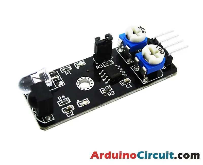
The KY-032 Obstacle Avoidance Sensor module is an electronic component that can detect obstacles and alert the robot or automation system to avoid them. The module is composed of a PCB board, an infrared sensor, a potentiometer, and a few other electronic components. The module can detect obstacles using infrared radiation and output a digital signal that can be read by a microcontroller or other electronic components.
Specifications
This module is equipped with a pair of infrared LEDs, including an emitter and a receiver. The emitter sends out pulses of infrared light at a specific frequency, which bounce off obstacles and return to the receiver LED.
The KY-032 module comes with four pins, including GND, +, S (out), and EN. By default, the module is always enabled and detecting obstacles. However, to control the state of the sensor, you can remove the jumper and use the EN pin. A HIGH signal will enable the sensor, while a LOW signal will disable it. You can adjust the detection distance by rotating the left knob, and for maximum distance, turn it to the middle. The right knob controls the frequency of the emitted IR pulse. To ensure the emitter works in tandem with the receiver, turn it clockwise all the way to set the emitter to the required frequency.
| Working voltage | 3.3V – 5V DC |
| Current Consumption | ≥ 20mA |
| Working temperature | -10°C – 50°C [14°F – 122°F] |
| Detection Range | 2cm – 40cm [0.79in – 15.75in] |
| IO interface | 4-wire interface (-/+/S/EN) |
| Output signal | TTL level (low level if obstacle detected, high if no obstacle) |
| Adjustment method | multi-turn resistance adjustment |
| IR pulse frequency | 38kHz according to HS0038DB datasheet |
| Effective angle | 35° |
| Board Size | 1.6cm x 4cm [0.62in x 1.57in] |
Features
- Highly sensitive to obstacles
- Adjustable detection range using a Potentiometer
- Low power consumption
- Easy to integrate with other electronic components
- Affordable and widely available
Pinout

Pin Configuration
| Pin Name | Pin Type |
|---|---|
| +V | Positive supply Pin |
| G | Ground Pin |
| A0 | Analog Pin |
| D0 | Digital Pin |
Circuit Diagram
The following circuit shows you the connection of the KY-032 Obstacle Avoidance Sensor Module with Arduino Please make the connection carefully

Circuit Connections
| Arduino | Module |
|---|---|
| +5V | +V Pin |
| GND | GND Pin |
| A0 | A0 |
| D0 | D0 |
Installing Arduino IDE Software
First, you will require to Download the updated version of Arduino IDE Software and Install it on your PC or laptop. if you Learn How to install the Arduino step-by-step guide then click on how to install Arduino Button given Blow
Code
The sensor’s output pin emits a LOW signal when it detects an obstacle, and a HIGH signal when no obstacle is detected or is out of range. In the example below, we’ll activate the LED on pin 13 of the Arduino when the sensor detects an obstacle.
Note that the code is intended to work with the jumper in place, so the sensor is always active. If you wish to control the sensor programmatically, remove the jumper and connect the sensor’s EN pin to pin 2 on the Arduino. Then, uncomment lines 4, 12, and 13 in the code.
//For more Projects: www.arduinocircuit.com
int ledPin = 13;      // LED pin on arduino
int detectorPin = 3;  // obstacle avoidance sensor interface
int val;              // variable to store result
//int enablePin = 2;  // sensor enable interface (EN)
void setup()
{
  pinMode(ledPin, OUTPUT);  // Define LED as output interface
  pinMode(detectorPin, INPUT);  // Define obstacle avoidance sensor as input interface

  // [uncomment and remove jumper on module to use enable pin (EN)]
  //pinMode(enablePin, OUTPUT);
  //digitalWrite(enablePin, HIGH);  // Enable sensor
}
void loop()
{
  val = digitalRead(detectorPin); // Read value from sensor
  if(val == LOW) // When the sensor detects an obstacle, the LED on the Arduino lights up
  {
    digitalWrite(ledPin, HIGH);
  }
  else
  {
    digitalWrite(ledPin, LOW);
  }
}
Applications
- Robotics
- Automation systems
- Smart homes and home automation
- Industrial automation
- DIY electronic projects
Conclusion
The KY-032 Obstacle Avoidance Sensor module is an essential electronic component in the field of robotics and automation. With its ability to detect obstacles and alert the robot or automation system to avoid them, it is a versatile and useful module that is widely used in a range of electronic projects. Whether you’re building a robot, an automation system, or a smart home automation device, the KY-032 Obstacle Avoidance Sensor module is a versatile and easy-to-use component that can help bring your projects to life.