
Introduction
In this tutorial, you will learn how to improve your Arduino programming: UART communication, Sending messages, and receiving data from the IDE’s serial monitor to your Arduino is a very common activity when developing a project. But what is behind the functions of the Serial set? In the following lines, we will develop step-by-step how an Arduino communicates with the PC through UART communication.
Hardware Required
| Components | # | Buy From Amazon |
|---|---|---|
| Arduino UNO | 2 | Buy Now |
| Led 5mm | 1 | Buy Now |
| Resistor 1K | 1 | Buy Now |
| 37 in 1 Sensors kit | 1 | Buy Now |
| Jumper Wires | few | Buy Now |
| Breadboard | 1 | Buy Now |
| 9v DC Adapter (Optional) | 1 | Buy Now |
Summary
In this article, we are going to review how data is transmitted and received in UART communication. UART stands for Universal Asynchronous Transmitter/Receiver or Universal Asynchronous Transmitter/Receiver. As such UART is not a protocol, but a device, which sometimes does not even need to be physically built into the microcontroller. Let me explain, the UART allows converting data from a register to a serial data transmission. That is, it takes the data from the register bit by bit and sends it over the transmission lines. Although it can be integrated through circuitry, it can also be implemented through code, taking data directly from the program and sending the serialized information to the receiver and vice versa.

The UART, being asynchronous, does not have a clock signal like the SPI protocol to indicate when to transmit each piece of data. Instead, the data itself has a start bit and a stop bit in its most common cases, there are also parity bits that indicate if the data is correct. In order for the two devices to communicate correctly, the transmission speed or “baud rate” must match. This allows the data to be read correctly, but if the baud rate is different, the received data will be misinterpreted.
The data sent in this communication has the following format: a start bit, data structure, parity bits, and stop bit. The data structure can have 5 or 9 data bits.

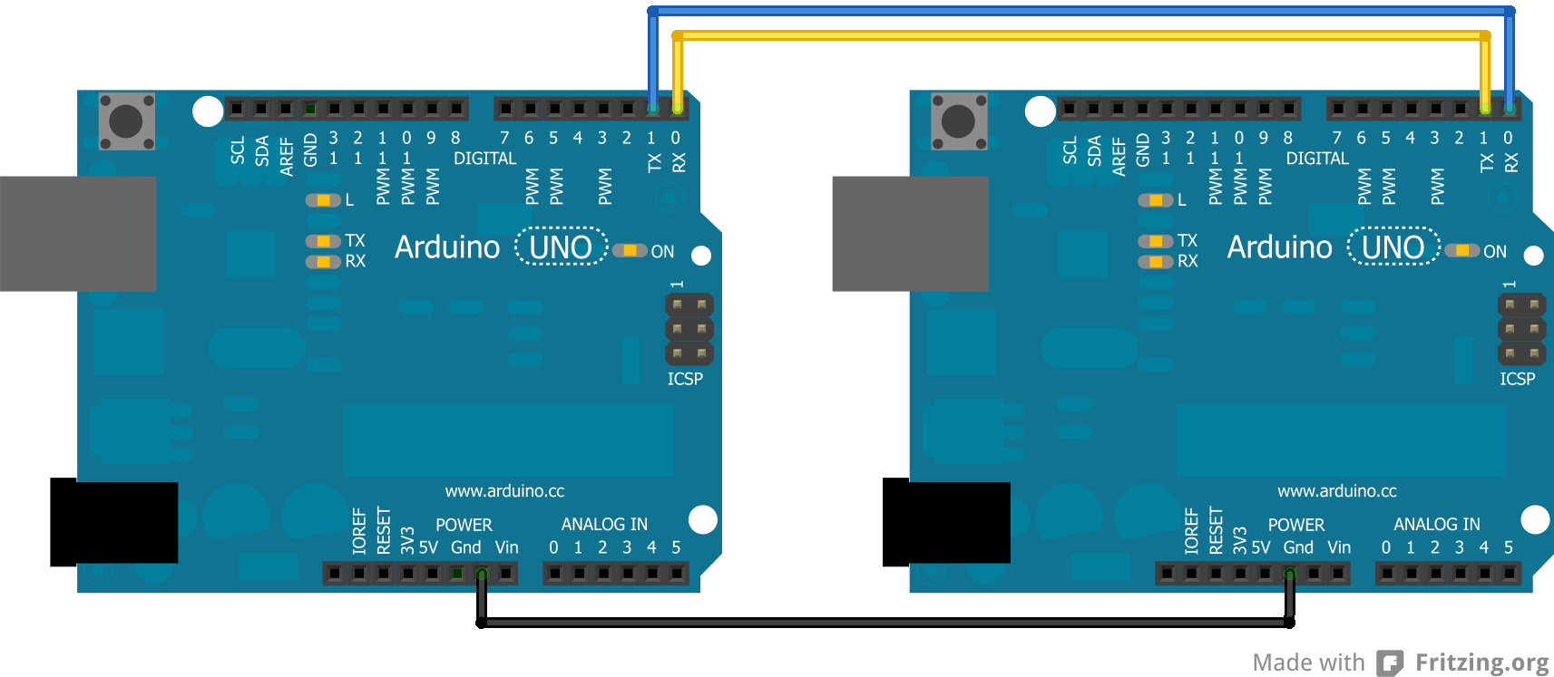
Circuit Diagram
The schematic below shows how to link the two Arduino together. This shows two Uno, but if a Mega is utilized here, it can be attached to any of the Serial ports on the Mega as long as that is accounted for in the code.

Installing Arduino IDE Software
First, you will require to Download the updated version of Arduino IDE Software and Install it on your PC or laptop. if you Learn How to install the Arduino step-by-step guide then click on how to install Arduino Button given Blow
Code For Sender
The sender code converts characters to bytes, and if necessary, number values to characters, before converting them into bytes.
//For more Projects: www.arduinocircuit.com

//Sender Code

char str[4];

void setup() {
  Serial.begin(9600);
}

void loop() {
  int value=1234; //this would be much more exciting if it was a sensor value

  itoa(value, str, 10); //Turn value into a character array
  Serial.write(str, 4);
}
Code For Receiver
The receiver code receives the byte array and interprets it. It is intended for use with a Mega, printing the received data to the Serial Monitor for debugging purposes. Paragraph 3: The debugging process can be avoided by using an Uno and displaying the received data on an I2C LCD screen.
//For more Projects: www.arduinocircuit.com

//Receiver Code

char str[4];

void setup() {
  Serial.begin(9600);
  Serial1.begin(9600);
}

void loop() {
  int i=0;

  if (Serial1.available()) {
    delay(100); //allows all serial sent to be received together
    while(Serial1.available() && i<4) {
      str[i++] = Serial1.read();
    }
    str[i++]='\0';
  }

  if(i>0) {
    Serial.println(str,4);
  }
}
Advantages of UART communication
- Only requires two cables
- Does not require a clock signal
- It has parity bits that prevent communication errors
- Well-documented and widely used method
Disadvantages
- Does not allow having multiple slave devices
- It does not allow simultaneous communication between master-slave, since they share the same data buffer
- Devices are commonly within short distances
As you can see, this type of communication is very useful when we want to implement communication between the PC and the microcontroller, and it is even possible to implement several UART “ports” by code if we manage to establish the correct packet structure and the baud rate matches. This tutorial for Improve your Arduino programming: UART communication

