
Introduction
Arduino is a popular microcontroller-based platform used by hobbyists and professionals alike to create a wide range of electronic projects. In this project, we will demonstrate how to use an Arduino board to control an LED ignition circuit using two push buttons. This simple project is a great introduction to using Arduino and can be easily adapted for a wide range of applications.
We will not use the usual external Pull-Up resistors on the buttons but we will exploit the internal resistors of the ATmega328P microcontroller. The pull-up is used to prevent the electrical and electromagnetic interferences present in the environment, introduced thanks to the very high impedance of the input pins, from causing random and involuntary commutations, by leaving the pin disconnected (this would occur with open contacts).
Arduino internally has a 20 Kohm pull-up resistor for each digital input, but it is inserted only with the appropriate instruction that we will see in the sketch.
Hardware Required
| Components | # | Buy From Amazon |
|---|---|---|
| Arduino UNO | 1 | Buy Now |
| LED 5mm (Red) | 3 | Buy Now |
| Resistors 220Ω | 3 | Buy Now |
| Buttons | 2 | Buy Now |
| Jumper Wires | Few | Buy Now |
| Breadboard | 1 | Buy Now |
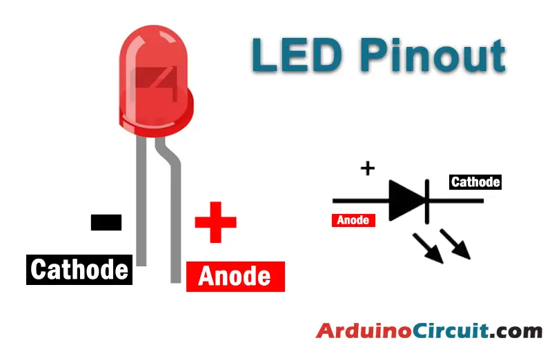
Pinout of LED
Pinout of Button

Working Explanations
The LED ignition circuit is controlled by two push buttons connected to the Arduino board. The first push button is used to turn the LED on, while the second push button is used to turn it off. When the “ON” button is pressed, the Arduino sends a signal to the LED to turn it on. The LED remains on until the “OFF” button is pressed, at which point the Arduino sends a signal to turn off the LED.
The code for this project is relatively simple, with two main functions used to control the LED ignition circuit. The first function is used to turn the LED on, while the second function is used to turn it off. When the “ON” button is pressed, the Arduino calls the “LED_ON” function, which sets the output pin connected to the LED to HIGH. Similarly, when the “OFF” button is pressed, the Arduino calls the “LED_OFF” function, which sets the output pin to LOW.
Circuit Diagram
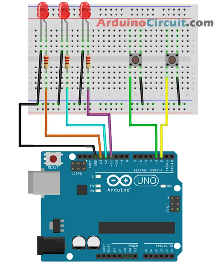
Circuit Connections
| Arduino | Buttons | LEDs |
|---|---|---|
| GND | 1st Pin oF Both Buttons | -Ve oF all LEDs |
| Pin 2 | 2nd Pin oF 1st Button | |
| Pin 3 | 2nd Pin oF 2nd Button | |
| Pin 11 | +Ve of 1st LED using R1 | |
| Pin 12 | +Ve of 2nd LED using R2 | |
| Pin 13 | +Ve of 3rd LED using R3 |
Installing Arduino IDE Software
First, you will require to Download the updated version of Arduino IDE Software and Install it on your PC or laptop. if you Learn How to install the Arduino step-by-step guide then click on how to install Arduino Button given Blow
Code
//For more Projects: www.arduinocircuit.com
/* In this example we will show how to select
the LED to turn on with two Up and Down buttons */
// Pin definition
int led1 = 11;
int led2 = 12;
int led3 = 13;
int buttonUp = 2;
int buttonDown = 3;
// Definition of the variables
int led = 1; // led to turn on
void setup() {
  // Set pins as outputs
  pinMode (led1, OUTPUT);
  pinMode (led2, OUTPUT);
  pinMode (led3, OUTPUT);
  // Setting the pins as inputs
  pinMode(buttonUp, INPUT);
  pinMode (buttonDown, INPUT);
  // Enabling of the internal PullUp resistors on the inputs
  digitalWrite(buttonUp, HIGH);
  digitalWrite(buttonDown, HIGH);
}
void loop() {
  if (digitalRead (buttonUp) == 0){ // if the button is pressed
    led++; // Increment the led variable
    if (led>3) { // If the variable exceeds the value 3
      led=1; // Reset the variable to 1
    }
    delay(500); // Pause for debounce
  }
if (digitalRead (buttonDown) == 0){ // if the button is pressed
    led--; // Decrement the led variable
    if (led<1) { // If the variable is less than the value 1
      led=3; // Reset the variable to 3
    }
    delay(500); // Pause for debounce
   }
   if (led==1) {
    digitalWrite(led1, HIGH); // Turn on led1
    digitalWrite (led2, LOW); // Turn off led2
    digitalWrite (led3, LOW); // Turn off led3
   }
   if (led==2) {
    digitalWrite(led1, LOW); // Turn off led1
    digitalWrite(led2, HIGH); // Turn on led2
    digitalWrite (led3, LOW); // Turn off led3
   }
   if (led==3) {
    digitalWrite(led1, LOW); // Turn off led1
    digitalWrite (led2, LOW); // Turn off led2
    digitalWrite(led3, HIGH); // Turn on led3
   }
}
Applications
- Alarm systems: The LED ignition circuit can be used as part of a simple alarm system, where the LED is turned on when motion is detected, and turned off when the motion stops.
- Lighting control: The LED ignition circuit can be used to control lighting in a room, where the “ON” button turns on a set of lights, and the “OFF” button turns them off.
- Doorbells: The LED ignition circuit can be used to trigger a doorbell, where pressing the “ON” button sends a signal to activate the doorbell, and pressing the “OFF” button turns it off.
- Robotics: The LED ignition circuit can be used as part of a larger robotics project, where the LED is used as a visual indicator for certain actions, such as when a robot arm is activated.
- Educational projects: The LED ignition circuit can be used as part of a simple electronics project for educational purposes, where students learn how to control electronic circuits using an Arduino board and push buttons.
Conclusion
In conclusion, this project demonstrates how to use an Arduino board to control an LED ignition circuit using two push buttons. The project is relatively simple, making it a great starting point for those new to Arduino, while also being adaptable for more complex projects. By following the steps outlined in this project, anyone can learn how to use Arduino to create a wide range of electronic projects.
See Also


